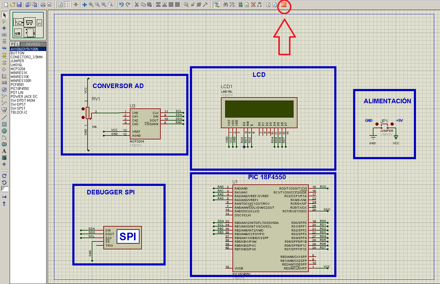
En este trabajo vamos a comunicar el PIC 18F4550 con el conversor analógico digital MCP3204 mediante el Bus SPI.
DATASHEET MCP3204
DATASHEET MCP3204
Los voltajes nos aparecerán en un LCD alfanumérico.
El bus interfaz con periféricos serie (SPI) fue desarrollado originalmente por Motorola a finales de los 80 en los microcontroladores serie 68000. Hoy en día se puede encontrar en teléfonos móviles, PDA, etc, para comunicar la CPU con los distintos periféricos.
El Bus SPI es un bus de tres líneas sobre el que se transmiten paquetes de información de 8bits. Cada dispositivo conectado al bus puede funcionar como transmisor y receptor al mismo tiempo, este tipo de comunicación se denomina full dúplex.
Hay dispositivos que solo son transmisores y otros solo receptores. Algunos, como las memorias EEPROM, son transmisores y receptores.
Los dispositivos conectados se pueden dividir en maestros y esclavos.
Los maestros son los que inician la transferencia de información y generan las señales de reloj y control.
Los esclavos son los dispositivos controlados por el maestro.
El bus utiliza las siguientes líneas:
Master Out - Slave In (MOSI): Conexión para la entrada de datos serie.
Master in- Slave out (MISO): Conexión para la salida de datos.
Clock (SCLK): Señal de reloj.
Slave select (SS): Seleccion.

Con respecto al I2C. el SPI alcanza velocidades muy superiors al utilizer lineas independientes de transmission y recepción.
En los PIC18 el SPI puede alcanzar frecuencias de 12 Mhz frente a 1Mhz del I2C.
La ventaja del I2C es que solo utiliza dos líneas, la de datos y la de reloj ( Sin contar GND) independientemente de los esclavos que tengas conectados dado que se seleccionan por software, por el contrario el SPI utiliza tres líneas para comunicarse y otra más para seleccionar.
Después de esta breve explicación del Bus SPI nos metemos ya en el programa.
En esta ocasión utilizaremos la librería del MCP3204 que viene con PIC C Compiler en “C:\Program Files (x86)\PICC\Drivers“ y así nos facilitará mucho las cosas para comunicarnos con el dispositivo.
La librería del MCP3204 es la siguiente:
////////////////////////////////////////////////////////////////////////////////////////////////////////////////////////////////////////
////////////////// Driver for MCP3204 A/D Converter ////////////////////////
//// ////
//// adc_init() ////
//// Call after power up ////
//// ////
//// value = read_analog_mcp( channel, mode ) ////
//// Read an analog channel ////
//// 0 through 3 and select ////
//// differential (0) or ////
//// single (1) mode ////
//// ////
//// value = read_analog( channel ) ////
//// Read an analog channel ////
//// 0 through 7 in single mode ////
//// ////
//// convert_to_volts( value, string ) ////
//// Fills in string with ////
//// the true voltage in ////
//// the form 0.000 ////
//// ////
////////////////////////////////////////////////////////////////////////////
//// (C) Copyright 1996,2003 Custom Computer Services ////
//// This source code may only be used by licensed users of the CCS C ////
//// compiler. This source code may only be distributed to other ////
//// licensed users of the CCS C compiler. No other use, reproduction ////
//// or distribution is permitted without written permission. ////
//// Derivative programs created using this software in object code ////
//// form are not restricted in any way. ////
////////////////////////////////////////////////////////////////////////////
#ifndef MCP3204_CS
#define MCP3204_CLK PIN_B1
#define MCP3204_DOUT PIN_C7
#define MCP3204_DIN PIN_B0
#define MCP3204_CS PIN_A0
#endif
void adc_init() {
output_high(MCP3204_CS);
}
void write_adc_byte(BYTE data_byte, BYTE number_of_bits) {
BYTE i;
delay_us(2);
for(i=0; i<number_of_bits; ++i) {
output_low(MCP3204_CLK);
if((data_byte & 1)==0)
output_low(MCP3204_DIN);
else
output_high(MCP3204_DIN);
data_byte=data_byte>>1;
delay_us(50);
output_high(MCP3204_CLK);
delay_us(50);
}
}
BYTE read_adc_byte(BYTE number_of_bits) {
BYTE i,data;
data=0;
for(i=0;i<number_of_bits;++i) {
output_low(MCP3204_CLK);
delay_us(50);
shift_left(&data,1,input(MCP3204_DOUT));
output_high(MCP3204_CLK);
delay_us(50);
}
return(data);
}
long int read_analog_mcp(BYTE channel, BYTE mode) {
int l;
long int h;
BYTE ctrl_bits;
delay_us(200);
if(mode!=0)
mode=1;
output_low(MCP3204_CLK);
output_high(MCP3204_DIN);
output_low(MCP3204_CS);
if(channel==1) // Change so MSB of channel #
ctrl_bits=4; // is in LSB place
else if(channel==3)
ctrl_bits=6;
else if(channel==4)
ctrl_bits=1;
else if(channel==6)
ctrl_bits=3;
else
ctrl_bits=channel;
ctrl_bits=ctrl_bits<<1;
if(mode==1) // In single mode
ctrl_bits |= 1;
else // In differential mode
ctrl_bits &= 0xfe;
ctrl_bits=ctrl_bits<<1; // Shift so LSB is start bit
ctrl_bits |= 1;
write_adc_byte( ctrl_bits, 7); // Send the control bits
h=read_adc_byte(4);
l=read_adc_byte(8);
output_high(MCP3204_CS);
return((h<<8)|l);
}
long int read_analog( BYTE channel ) // Auto specifies single mode
{
long int temp;
if(channel<4)
temp=read_analog_mcp( channel, 1);
else
temp=0;
return temp;
}
void convert_to_volts( long int data, char volts[6]) {
BYTE i, d, div_h, div_l;
long int temp,div;
div=4095/5.00;
if(data>=4090)
data=4095;
for(i=0;i<=4;i++) {
temp=data/div;
volts[i]=(BYTE)temp+'0';
if(i==0) {
volts[1]='.';
i++;
}
temp=div*(BYTE)temp;
data=data-temp;
div=div/10;
}
volts[i]='\0';
}
////////////////////////////////////////////////////////////////////////////////////////////////////////////////////////////////////////
También usaremos la librería del LCD alfanumérico:
////////////////////////////////////////////////////////////////////////////////////////////////////////////////////////////////////////
// flex_lcd.c
// These pins are for the Microchip PicDem2-Plus board,
// which is what I used to test the driver. Change these
// pins to fit your own board.
#define LCD_DB4 PIN_D4
#define LCD_DB5 PIN_D5
#define LCD_DB6 PIN_D6
#define LCD_DB7 PIN_D7
//
#define LCD_RS PIN_D0
#define LCD_RW PIN_D1
#define LCD_E PIN_D2
// If you only want a 6-pin interface to your LCD, then
// connect the R/W pin on the LCD to ground, and comment
// out the following line.
#define USE_LCD_RW 1
//========================================
#define lcd_type 2 // 0=5x7, 1=5x10, 2=2 lines
#define lcd_line_two 0x40 // LCD RAM address for the 2nd line
int8 const LCD_INIT_STRING[4] =
{
0x20 | (lcd_type << 2), // Func set: 4-bit, 2 lines, 5x8 dots
0xc, // Display on
1, // Clear display
6 // Increment cursor
};
//-------------------------------------
void lcd_send_nibble(int8 nibble)
{
// Note: !! converts an integer expression
// to a boolean (1 or 0).
output_bit(LCD_DB4, !!(nibble & 1));
output_bit(LCD_DB5, !!(nibble & 2));
output_bit(LCD_DB6, !!(nibble & 4));
output_bit(LCD_DB7, !!(nibble & 8));
delay_cycles(1);
output_high(LCD_E);
delay_us(2);
output_low(LCD_E);
}
//-----------------------------------
// This sub-routine is only called by lcd_read_byte().
// It's not a stand-alone routine. For example, the
// R/W signal is set high by lcd_read_byte() before
// this routine is called.
#ifdef USE_LCD_RW
int8 lcd_read_nibble(void)
{
int8 retval;
// Create bit variables so that we can easily set
// individual bits in the retval variable.
#bit retval_0 = retval.0
#bit retval_1 = retval.1
#bit retval_2 = retval.2
#bit retval_3 = retval.3
retval = 0;
output_high(LCD_E);
delay_cycles(1);
retval_0 = input(LCD_DB4);
retval_1 = input(LCD_DB5);
retval_2 = input(LCD_DB6);
retval_3 = input(LCD_DB7);
output_low(LCD_E);
return(retval);
}
#endif
//---------------------------------------
// Read a byte from the LCD and return it.
#ifdef USE_LCD_RW
int8 lcd_read_byte(void)
{
int8 low;
int8 high;
output_high(LCD_RW);
delay_cycles(1);
high = lcd_read_nibble();
low = lcd_read_nibble();
return( (high<<4) | low);
}
#endif
//----------------------------------------
// Send a byte to the LCD.
void lcd_send_byte(int8 address, int8 n)
{
output_low(LCD_RS);
#ifdef USE_LCD_RW
while(bit_test(lcd_read_byte(),7)) ;
#else
delay_us(60);
#endif
if(address)
output_high(LCD_RS);
else
output_low(LCD_RS);
delay_cycles(1);
#ifdef USE_LCD_RW
output_low(LCD_RW);
delay_cycles(1);
#endif
output_low(LCD_E);
lcd_send_nibble(n >> 4);
lcd_send_nibble(n & 0xf);
}
//----------------------------
void lcd_init(void)
{
int8 i;
output_low(LCD_RS);
#ifdef USE_LCD_RW
output_low(LCD_RW);
#endif
output_low(LCD_E);
delay_ms(15);
for(i=0 ;i < 3; i++)
{
lcd_send_nibble(0x03);
delay_ms(5);
}
lcd_send_nibble(0x02);
for(i=0; i < sizeof(LCD_INIT_STRING); i++)
{
lcd_send_byte(0, LCD_INIT_STRING[i]);
// If the R/W signal is not used, then
// the busy bit can't be polled. One of
// the init commands takes longer than
// the hard-coded delay of 60 us, so in
// that case, lets just do a 5 ms delay
// after all four of them.
#ifndef USE_LCD_RW
delay_ms(5);
#endif
}
}
//----------------------------
void lcd_gotoxy(int8 x, int8 y)
{
int8 address;
if(y != 1)
address = lcd_line_two;
else
address=0;
address += x-1;
lcd_send_byte(0, 0x80 | address);
}
//-----------------------------
void lcd_putc(char c)
{
switch(c)
{
case '\f':
lcd_send_byte(0,1);
delay_ms(2);
break;
case '\n':
lcd_gotoxy(1,2);
break;
case '\b':
lcd_send_byte(0,0x10);
break;
default:
lcd_send_byte(1,c);
break;
}
}
//------------------------------
#ifdef USE_LCD_RW
char lcd_getc(int8 x, int8 y)
{
char value;
lcd_gotoxy(x,y);
// Wait until busy flag is low.
while(bit_test(lcd_read_byte(),7));
output_high(LCD_RS);
value = lcd_read_byte();
output_low(lcd_RS);
return(value);
}
#endif
void lcd_setcursor_vb(short visible, short blink) {
lcd_send_byte(0, 0xC|(visible<<1)|blink);
}
////////////////////////////////////////////////////////////////////////////////////////////////////////////////////////////////////////
Y aquí el programa principal:
////////////////////////////////////////////////////////////////////////////////////////////////////////////////////////////////////////
////////////////////////////////////////////////////////////////////////////////////
// AUTOR: José Antonio Pelayo NOVIEMBRE/2011
////////////////////////////////////////////////////////////////////////////////////
// PROGRAMA: Conversor analogico/digital SPI VERSIÓN: 1.0
// DISPOSITIVO: PIC 18F4550 COMPILADOR: CCS vs4.109
// Entorno IDE: MPLAB SIMULADOR: Proteus 7.7 sp2
// TARJETA DE APLICACIÓN: ___ DEBUGGER: ICD3
/////////////////////////////////////////////////////////////////////////////////
/////////////////////////////////////////////////////////////////////////////////
/////////////////////////////////////////////////////////////////////////////////
/////////////////////////////////////////////////////////////////////////////////
//
//
// Conversor analogico Digital mediante el bus SPI(Maestro) Y CAD MCP3204 ///////
//
//////////////////////////////////////////////////////////////////////////////////
#include <c:\h\18F4550.h>
#fuses INTHS //Selecciona el oscilador interno
//#FUSES HS //External clock
#FUSES MCLR //Master Clear pin enabled
//#use delay(clock=4000000)
#use delay(internal=4000000hz) // Selecciona la velocidad del oscilador interno
#include <LCD_flexible_1.c>
#include <mcp3204_1.c>
//#byte ucfg= 0xf6f //Para poder utilizar RC4 y RC5 (en modo TTL, sólo pueden ser entradas)
////////////////////////////////////////////////////////////////////////////////////
// VARIABLES GLOBALES //////////////////////////////////////////////////////////////
////////////////////////////////////////////////////////////////////////////////////
char string[6];
float valor;
float voltios;
////////////////////////////////////////////////////////////////////////////////////
// PRINCIPAL ///////////////////////////////////////////////////////////////////////
////////////////////////////////////////////////////////////////////////////////////
void main()
{
lcd_init();
adc_init();
for(;;)
{
valor=read_analog(0);//lectura del canal 0 del MCP3204
DELAY_MS(50);
lcd_gotoxy(1,1);
convert_to_volts( valor,string );// Llamada a una función de la librería del MCP3204 para que nos de los //voltios en un array.
printf(lcd_putc," %s Voltios",string);//mostramos el array con los voltios
lcd_gotoxy(1,2);
printf(lcd_putc,"Jose Pelayo");
DELAY_MS(100);
}
}
////////////////////////////////////////////////////////////////////////////////////////////////////////////////////////////////////////
En esta ocasión, además del diseño en Proteus para su simulación, también hemos trabajado con Ares.
Para pasar un diseño en Proteus a Ares seguiremos estos pasos:
Una vez tengamos ya todo el diseño daremos en “ Netlist Transfer to ARES “.
Una vez se nos abre el Ares, clicamos en “ Component Mode “ y vamos colocando los componentes .
Para hacer el contorno seleccionamos “ 2D graphics Box Mode ” y “ Board Edge “.

También podemos perforar nuestra placa para sujetarla después
con los “ Through Hole “ .

Para modificar los tamaños que vamos a utilizar en las pistas, capas que va a tener nuestro diseño , etc , clicamos en “ Desing Rule Manager “ .

T40 equivale a 1mm, las capas que vamos a utilizar son la Top y la Botton.
Una vez hecho esto vamos a rutear automáticamente, para ello vamos a "Shape Based Auto Router " .

Si queremos poner alguna indicación en la cara TOP podemos hacerlo de la siguiente manera, en este diseño he indicado donde conectar +5v y GND para alimentar la placa.
Seleccionamos " 2D graphics Text Mode " y la cara TOP.

Si queremos hacer el plano de masa clicamos en “ Tools/ Power Plane Generator “.


Finalmente el diseño ha quedado así.

Para verlo en 3D clicamos en “ Output/3D Visualization “ .


Y con esto ya está finalizado este pequeño diseño en Ares.
Video de simulación en Proteus:
Video en tarjeta:
